
















A Practical Guide to Automatic Screw Feeding Systems for Assembly Lines
How does an automatic screw feeding system take loose screws from a hopper and deliver them individually to the tightening position? Sorting, separation, delivery and positioning mechanisms work in sequence to make this happen. The screw’s shape and the location of the joint help determine which feeding method is suitable.
This guide follows those stages to explain how automatic screw feeding works, using Leetx solutions to illustrate how blow feeding, vacuum holding and other handling methods fit into assembly operations.
How Screws Move Through an Automatic Feeding System
A typical feeding sequence follows this path:
Bulk storage → Orientation → Separation → Delivery → Holding and positioning → Tightening
Each stage prepares the screw for the next. Orientation establishes a usable position; separation releases an individual fastener; delivery moves it towards the tool; and the end module holds it during approach to the joint.
The arrangement varies by application. Some systems blow screws through a tube to the tightening module. Others present them at a fixed pickup point, where a tool collects each screw before moving to the workpiece.
Vacuum holding can be used at the tool end, including in systems that also use blow feeding. These functions address different tasks: one transports the screw, while the other holds it for positioning.
Understanding that distinction makes it easier to assess how an automatic screw feeding system fits into the complete assembly process.

How Screw Sorting, Separation and Delivery Work
Orienting Screws for Consistent Feeding
Loose screws enter the hopper in mixed positions. Before they can move through a controlled delivery path, they need to be arranged consistently.
Guide tracks use the geometry of the screw head and shank to establish a usable orientation. Head diameter, shank length, washers and other features influence how the fastener rests on the track and moves towards the separation mechanism.
Our FLH step feeder uses stepped lifting followed by linear vibratory orientation. Screws then move towards individual separation and tube delivery. For coated or appearance-sensitive fasteners, trials can also examine surface condition after handling.
The purpose of this stage is to maintain a supply of correctly presented screws. Moving bulk fasteners quickly is useful only when the next mechanism receives them in the required orientation.
Separating and Delivering Individual Screws
The separation mechanism releases one screw from the waiting supply. In a blow-fed arrangement, that screw enters the delivery tube and travels towards the tool head.
The tube is part of the working mechanism. Its internal dimensions, routing and connection points need to suit both the fastener and the machine layout. A route tested on a bench may behave differently once installed around guarding, moving axes and production tooling.
A representative trial should therefore include the intended tube route wherever practical. If the tube is attached to a moving tool, the trial should also cover that movement.
For fixed pickup arrangements, the screw is presented at a defined location instead. The tool must collect it reliably before travelling to the joint, making pickup position and tool travel part of the operating sequence.
Holding the Screw During Tool Approach
Once the screw reaches the tool, it must remain correctly positioned during approach and engagement.
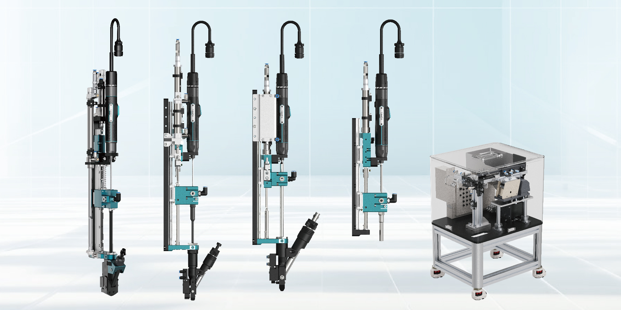
The Leetx AIV-AT vacuum tightening module combines blow delivery with vacuum holding at the tool end. It includes suction detection and adjustable downward force, with vacuum-tube configurations for screw heads up to 14 mm in diameter.
Blow feeding brings the screw to the module; vacuum holding secures it for movement towards the workpiece. The final configuration depends on the fastener and the surrounding geometry.
The tool must reach the joint, engage the drive and withdraw after tightening. All three movements should be considered when developing the end-module arrangement.
How Screw Dimensions and Coatings Affect Feeding
Thread size alone does not describe how a screw will feed.
Two M4 screws may have different head diameters, shank lengths or washers. Those differences can affect orientation on a track, passage through a tube and engagement with the end module.
A useful way to examine a fastener is to follow its contact points through the system:
- Where does it rest during orientation?
- Which dimensions determine clearance through the delivery path?
- How is it retained at the tool?
- What guides it as it enters the joint?
A captive washer needs particular attention because both the screw and washer must pass through the handling sequence. A short screw may also need a different delivery arrangement from a longer fastener with the same thread size.
Surface requirements add another consideration. For coated screws, inspect the relevant surfaces before and after feeding. Where appearance or coating integrity forms part of product acceptance, use those requirements to judge the result.
Drawings and production samples serve different purposes here. Drawings establish dimensions and tolerances; samples show how the supplied fasteners behave during actual handling.

Delivering Screws to Recessed and Obstructed Holes
A successful delivery test confirms that the screw reaches the tool. The next step is to check whether the complete module can reach the assembly position.
Housing walls, ribs, fixtures and adjacent components can restrict access. Engineers therefore need the surrounding geometry, not just the hole diameter and depth.
Consider a screw positioned below the edge of a housing. The driver may be narrow enough to reach it, while the screw-holding mechanism needs more clearance. In this situation, the end module’s shape and holding method become central to the design.
Review the complete movement:
Approach: Check the module body, connections and tubing along the path towards the joint.
Engagement: Examine screw alignment, available clearance and how the fastener is held as it enters.
Withdrawal: Confirm that the tool can leave the completed joint and move towards its next position.
For external-drive fasteners, socket engagement adds another consideration. The socket approach, fastener position and available movement need to be evaluated together.
Leetx’s tightening modules and feeding accessories allow these requirements to be addressed alongside the feeding method, while the station layout is still being developed.

Coordinating Screw Feeding with the Assembly Cycle
Feeder output and station output measure different things.
A feeder may prepare screws faster than the station consumes them. The station must also move, locate the tool, tighten the joint, evaluate the result and release or reposition the workpiece.
For example, a robot using a fixed pickup point must travel to collect each screw before returning to the joint. In a blow-fed arrangement, the screw travels to the tool, but the cycle still depends on delivery, positioning and tightening time.
Comparing these complete sequences shows where time is spent and whether another operation can take place while the next screw is being prepared.
Where the equipment design allows overlapping actions, the control sequence must establish when delivery is permitted and when the tool is ready to proceed. If the station regularly waits before tightening, examine the sequence before increasing feeder speed.
Useful observations include:
- When the station requests the next screw.
- When the screw reaches the tool or pickup point.
- How long the tool spends travelling between positions.
- Which conditions must be satisfied before tightening starts.
- How the station resumes after an interrupted cycle.
After a stop, the station should resume from a known state. Depending on the design, this may involve checking whether a screw is already present before requesting another.
Clear sequencing makes waiting time easier to investigate and helps operators understand what the station is doing.
Integrating Screw Feeding into Different Assembly Stations
Handheld Screwdriving Stations
Automatic feeding reduces repeated screw pickup and placement in a handheld station. Tool balance, tube routing and movement between joints still affect how comfortably the operator can work.
A tube that appears easy to route on a drawing may restrict reach when the operator moves around a larger product. A practical assessment should include the intended working posture and the normal sequence of fastening positions.
The location of the feeder also matters for replenishment and routine access. These tasks should fit the workstation without interfering with assembly movements.
Fixed and Robotic Screwdriving Stations
A fixed station relies on consistent workpiece location. The fixture, clamping arrangement and tool approach form part of the feeding and tightening process.
Robot applications introduce travel and changes in tool orientation. Load assessment needs to include the tightening tool, feeding module, mounting hardware, attachments and tubing, together with centre of gravity and inertia.
In both arrangements, leave access for inspection, cleaning and maintenance. A compact layout should still allow the production team to reach the components they need to service.
Stations Using Multiple Screw Types
Batch changeover and mixed-fastener assembly create different demands.
For batch changeover, identify the components and settings that change, how remaining screws are cleared and how the new configuration is checked.
When one product uses several screw types in the same cycle, the selected fastener must correspond to the correct tool position and program. Depending on the application, this may involve separate feeding paths or pickup locations.
Test the changeover procedure as an operation in its own right. The assessment should cover the steps needed to stop the current batch, make the change and return to production with the correct configuration.
Testing Screw Feeding Under Production Conditions
A useful feeding trial answers a defined engineering question.
For one application, that may be whether a coated screw can pass through the complete route with an acceptable surface finish. For another, it may be whether the end module can reach a recessed joint within the required cycle.
NIST’s guidance on experimental design begins with objectives, followed by the selection of variables and a test design. Applied to a feeding trial, this means deciding what needs to be learned before choosing the conditions.
Keep observations tied to the stage where they occur. If delivery pauses, record whether the screw stopped during orientation, separation, tube travel or reception at the end module. Include the fastener type, setup and relevant operating conditions.
This gives engineers a specific starting point for adjustments. They can modify the affected part of the process and repeat the relevant test, rather than changing several settings without knowing which one influenced the result.
The people who will run and maintain the station should also take part. Their assessment of replenishment, access and recovery procedures complements the engineering measurements.
The most useful trial follows the screw all the way to a completed joint. It checks delivery, surface condition, tool access and cycle timing in the same setup. At Leetx, we use this complete view of the application to match the feeder and tightening module to the work the station needs to perform.
FAQ About Automatic Screw Feeding Systems
Q1: How Does an Automatic Screw Feeding System Work?
It arranges loose screws into a usable orientation, separates them individually and delivers them to a tool or pickup position. The end module then holds and positions the screw for tightening. The exact sequence depends on the fastener and station design.
Q2: Are Blow Feeding and Vacuum Holding Alternative Methods?
They can be combined. Blow feeding transports a screw through a tube, while vacuum holding secures it at the tool end. Leetx’s AIV-AT module uses both functions within the same delivery and positioning sequence.
Q3: Can Screws with the Same Thread Size Use the Same Feeder Setup?
Sometimes, but thread size is only one factor. Head dimensions, length, washers and surface condition also affect handling. Drawings and representative samples help establish whether the same setup can accommodate both fasteners.
Q4: Why Does Feeder Speed Differ from Assembly Output?
Assembly output includes movement, positioning, tightening and workpiece handling as well as feeding. Some operations may overlap, while others must happen in sequence. The complete station cycle determines production output.