















Automatic Screwdriving System Components: Feeder, Driver and Controller Explained
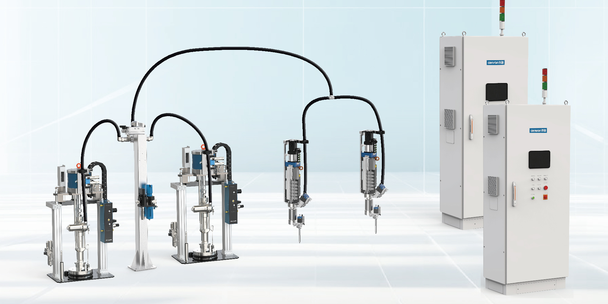
An automatic screwdriving system consists of four component groups that orient, feed, drive and monitor fasteners without manual handling: a feeding and singulation unit, a screwdriver unit with its working head, positioning hardware, and a controller. A system is integrated when these four are designed around one fastening sequence rather than assembled from separate suppliers.
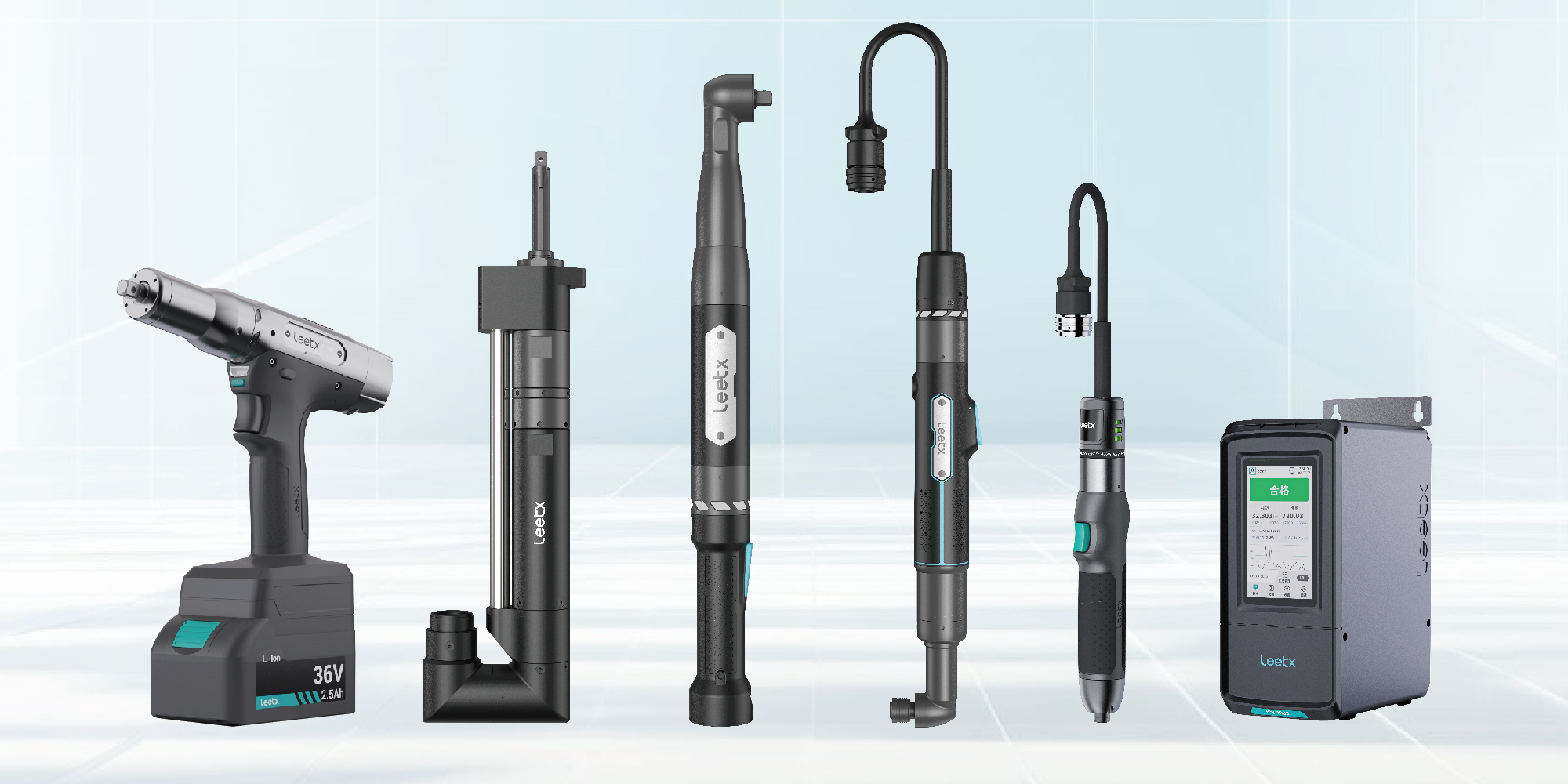
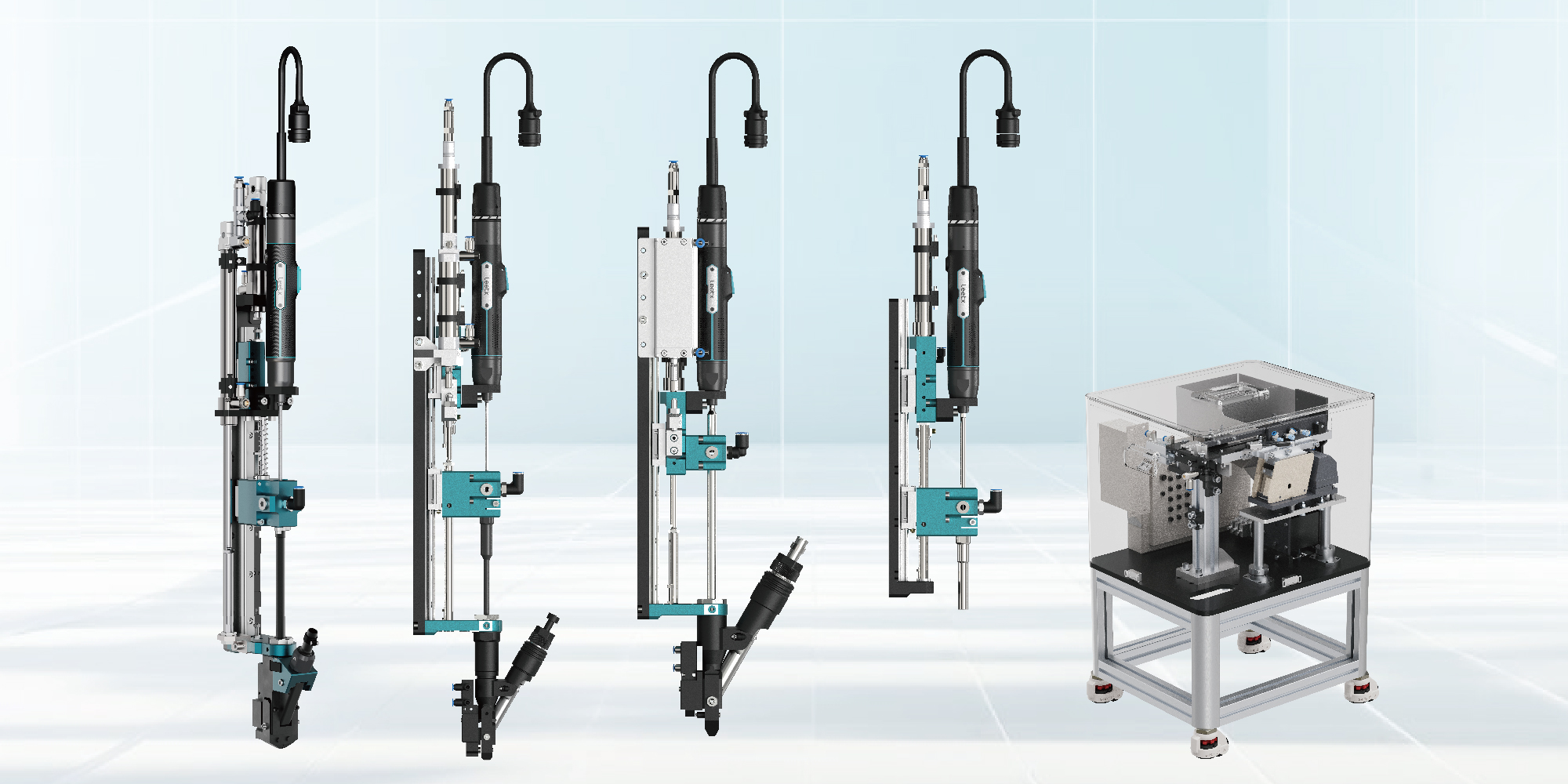
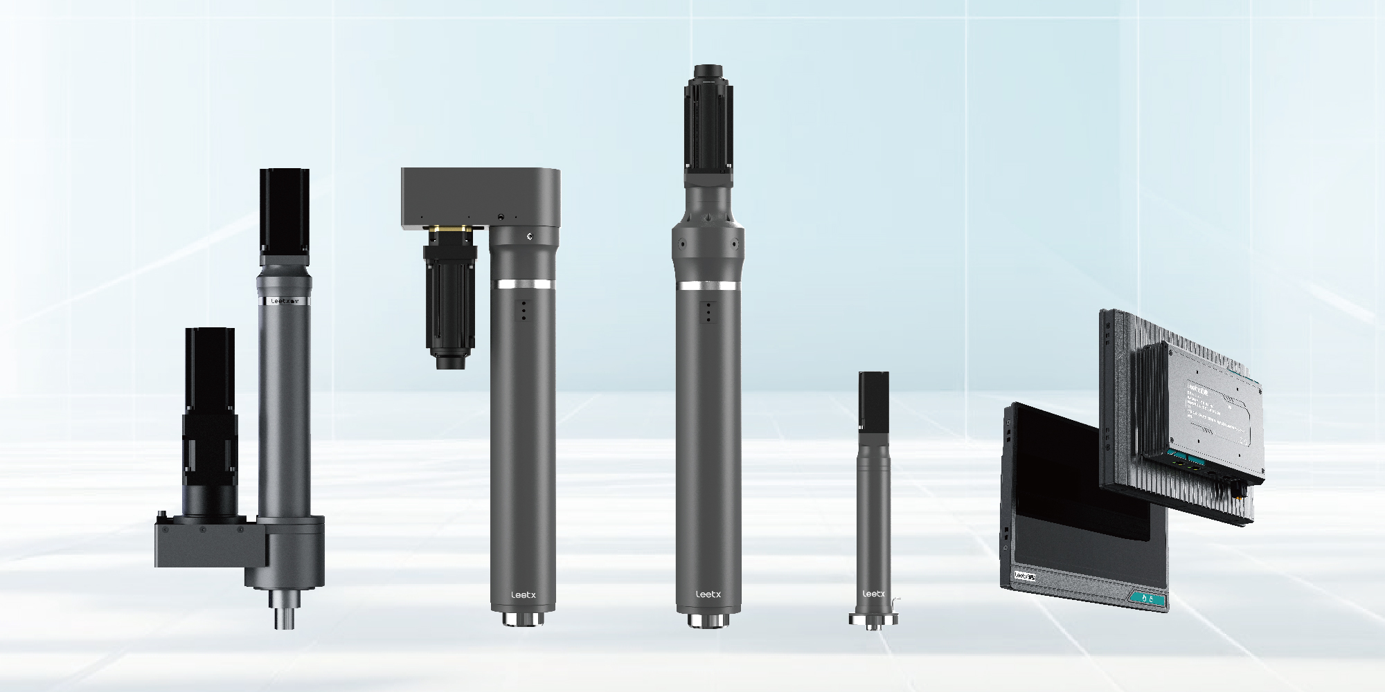
Leetx supplies all four groups within its Automatic Screw Feeding System and Transducerized Tightening System: step, bowl and presenter feeding units; blow-feed and vacuum tightening modules with EHS and IHS screwdrivers; handheld, fixtured and robotic mounting options; and the TCS.2000 tightening controller with the FSC-2000 feeding controller.
This article describes what each group does, where the handovers between them sit, and how a Leetx configuration covers the sequence from hopper to recorded result.
The Four Component Groups
The groups are listed in the order a screw passes through them. Each handover between groups is a point where the station needs a defined signal, not an assumption.

Feeding and Singulation: From Bulk to a Single Oriented Screw
Bulk feeding turns loose fasteners into a controlled supply. The hopper holds stock and refills the feeder; the feeder orients screws and presents them in a track; the escapement isolates one screw per request; the feed tube or presenter carries it to the working head.
Leetx offers two feeding principles. The FLH step feeder lifts screws in stages onto a linear track with a short agitation cycle, which suits coated screws and cleanliness-sensitive assembly in M3–M8. The bowl feeder uses continuous vibration and suits general applications. For screws too short to blow-feed, the TF90 presenter presents M2–M6 screws at a pick-up position instead of a tube.
The handover to the working head is where integration starts. A feed request initiates delivery; a confirmation that the screw has arrived and is retained is what allows the next step. If no screw is available, the fault sits in supply and separation; if a screw was delivered but not retained, it sits at the head. Keeping those two signals separate is what lets maintenance find the problem without resetting the whole station.

Screwdriver Unit and Working Head: Receiving, Holding and Driving
The screwdriver unit combines a transducerized EHS screwdriver, which measures torque and angle during the drive, with a working head that receives and holds the screw. The head design follows how the screw arrives and how much space surrounds the joint.
Blow delivery with a jaw head
The ASG standard module receives a blow-fed screw in a sprung jaw at the tool head and drives it down. This is the default for accessible joints where the jaw can approach the hole.
Vacuum transfer to a recessed joint
The AIV-AT internal-drive vacuum module receives the blow-fed screw, then holds it with a vacuum tube that can match the screw-head diameter and extends it to the workpiece. The module is designed for applications with 90° and 360° obstructions and accommodates screws with a maximum head diameter of 14 mm. Suction detection confirms the screw is held before the drive starts; downward force is adjustable; the module includes screw drop prevention. The AOV module does the same for external-drive screws, with a floating socket that aligns to the head before torque is applied.
Pick-up from a presenter
The APP vacuum pick-and-place module travels to a presentation position, lifts the screw by vacuum and carries it to the joint. It is used where screws cannot be blow-fed, and in the APP-Q version exchanges heads automatically for several screw types.
In every case the working head must reach the joint with the bit, tube and screw clear of interference during approach, drive and withdrawal. Delivery method and joint access are one design decision, not two.

Positioning Hardware: Handheld, Fixtured and Robotic
The same screwdriver unit and head are mounted in three ways, depending on who or what positions the tool.
Handheld. The AHB, AHV-AT and AHP modules are used with a torque arm that carries the weight and absorbs reaction. With position sensing on the arm, the station also knows which hole the tool is over, which provides position error-proofing.
Fixtured. Modules mount on a linear axis or gantry above a part fixture. For multi-joint patterns, EFS tightening spindles run in a master-slave configuration of up to 20 spindles, with parameters set once on the master and every spindle's status visible in real time.
Robotic. The AIV-AT variant weighs under 3 kg without the tool and under 4 kg with an EHS or IHS screwdriver, for collaborative robots with standard interfaces. Total end-of-arm load, centre of gravity and reach are confirmed on the cell.
Positioning hardware determines cycle time more often than the screwdriver does. Movement between joints, approach and withdrawal usually outweigh the drive itself.
Control: From Tightening Result to Station Decision
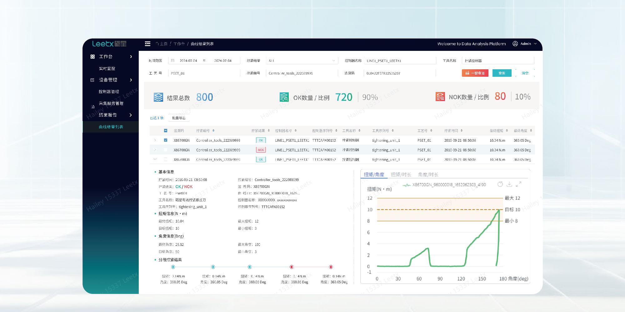
Two controllers divide the work. The FSC-2000 feeding controller runs the feeding chain, including escapement, tube accessories, counting and refill alarms, and operates standalone with the FSC-TP pendant for setup. The TCS.2000 tightening controller runs the tightening program, judges each result and records it, with Ethernet, Web API, Open Protocol and optional fieldbus for the station PLC or MES.
An integrated sequence makes four states explicit:
- The workpiece and working head reach the required state, and a screw is confirmed at the head.
- The correct tightening program is selected and the drive starts.
- The result for that joint becomes available: OK/NOK, torque, angle and curve.
- The station applies its decision: continue, hold the assembly, or enter a defined recovery sequence.
A station that moves on after a movement-complete signal alone has not established whether the joint met its requirements. The result has to be part of production control, not information displayed after the part has left. How those results are stored and traced is covered in Leetx's article on tightening data collection and traceability.

Recovery After an Interrupted Cycle
Interruptions leave different physical states, and the recovery action has to follow the state of the screw and joint.
Operator messages should distinguish these cases. "Feed not confirmed" and "tightening interrupted" point to different components, and a message that names the affected operation and the permitted next step restores the station without losing its process history.
What Leetx Supplies and What the Cell Adds
Leetx supplies the four component groups as one configuration: feeding unit, tightening module and screwdriver, mounting option, and both controllers, with the handovers between them defined in the FSC-2000 and TCS.2000 settings. That is the basis for an automatic screwdriving station.
The complete cell adds part fixtures, positioning axes or a robot, guarding and the connection to plant systems, which usually sit with the machine builder. Defining that boundary early keeps a complete component list from concealing unfinished station engineering.
To configure an automatic screwdriving system for a specific product, share the screw specifications, joint access conditions, cycle time target and intended mounting with Leetx. Leetx proposes the component combination and validates the sequence on the customer's fasteners before the station design is fixed.
FAQ About Automatic Screwdriving System Components
Q1: What Are the Main Components of an Automatic Screwdriving System?
A feeding and singulation unit, a screwdriver unit with its working head, positioning hardware, and a controller. Leetx covers them with step, bowl and presenter feeders, EHS screwdrivers on ASG, AIV-AT, AOV or APP modules, handheld, fixtured and robotic mounting, and the TCS.2000 and FSC-2000 controllers.
Q2: Why Do the Feeding Controller and Tightening Controller Stay Separate?
Feeding and tightening are different control loops: one sequences delivery and refill, the other runs the torque program and judges the joint. Separating them keeps the feeding logic out of the station PLC and keeps tightening results tied to the joint. The two exchange defined signals for screw-ready and cycle-complete.
Q3: Which Leetx Working Head Suits a Recessed or Obstructed Joint?
The AIV-AT for internal-drive screws and the AOV for external-drive screws. Both hold the screw by vacuum at a head sized to the screw, so the tool reaches positions a jaw head cannot.