















Servo vs. Hydraulic vs. Pneumatic Presses: How Force Control Differs in Precision Press-Fit
Pneumatic, hydraulic and servo presses generate force in three different ways, and the way force is generated decides how precisely it can be controlled. A pneumatic cylinder converts air pressure into force; a hydraulic cylinder does the same with oil at higher pressure; a servo press converts motor torque into linear force through a ball screw, with position and force measured continuously.
For precision press-fit assembly, the main advantage of a servo press is precise control of force and position throughout the stroke. When pressing a bearing, bushing or pin, this allows the approach speed, pressing force and stopping position to be matched to the assembly requirements. Software extends that control with programmable pressing sequences, process evaluation and traceable records. The electric drive also eliminates the need for a hydraulic oil circuit, supporting a cleaner production environment.
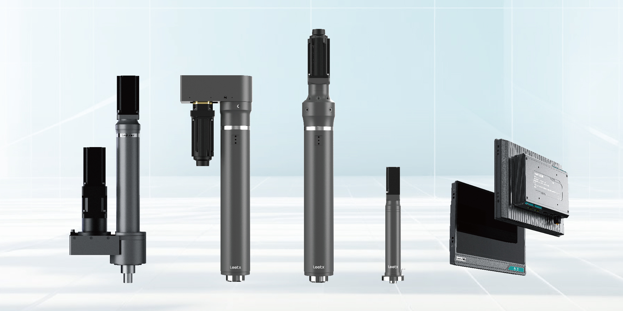
Leetx combines these capabilities in its AEPS servo press and Acquisition and Evaluation System. The following comparison explains how the three drive types differ in force and position control, how software supports process monitoring, and what those differences mean for precision assembly.
How Each Drive Type Produces and Controls Force
Pneumatic. Force equals air pressure times piston area. Pressure is set by a regulator, so the press delivers roughly one force per setting, and the ram travels until it meets resistance or a hard stop. Speed depends on flow and load. There is no inherent position control; depth is set mechanically.
Hydraulic. Force equals oil pressure times piston area, with pressure set by a relief valve or proportional valve. Much higher forces are available in a compact cylinder. Position and speed can be controlled with proportional valves and transducers, but the control acts on a compressible fluid column, and response is limited by valve dynamics and oil temperature.
Servo. A servo motor drives a ball screw; an encoder reports position and a force sensor reports load, both continuously. The controller can command position, speed or force at any point in the stroke and switch between them mid-cycle. Force is a controlled variable rather than a consequence of pressure.
The rest of the comparison follows from these three descriptions.

1. Contact and Force Build-Up
Press-fit quality is decided in the first millimetre after contact. The ram meets the part, resistance rises, and the controller has to respond before the force runs past its target.
A pneumatic press arrives at whatever speed the flow allows and converts its kinetic energy into a force spike at contact. A hydraulic press can be slowed by valve control, but the fluid column and valve response set the limit. A servo press decelerates by command: approach fast in free travel, slow before contact, press under control.
Leetx's evaluation system adds adaptive deceleration control, which adjusts approach speed to the part's force development as contact is detected. The stated effect is force overshoot held within 1%.
2. Overshoot and Part Protection
Overshoot is the transient peak above the target during the transition into load. It comes from the moving mass, elastic energy stored in the frame and tooling, and the delay between measuring force and changing motion.
With a pneumatic press the peak is uncontrolled; parts that cannot tolerate it need mechanical stops. With a hydraulic press the peak depends on valve response and is usually larger than the settled value. With a servo press the peak is managed by the approach profile and the controller's response, and it is measured, so an exceeded limit is a recorded event rather than an unnoticed one.
For components with an allowable load limit, acceptance has to cover the transient peak as well as the final force. Only a drive that measures continuously can show both.
3. Holding Force Under Load
Some joints require a dwell under load after the target is reached. The requirement is a force band and a duration, not a position.
A pneumatic press holds pressure well, but the force is fixed by the regulator and any part relaxation goes uncorrected. A hydraulic press holds force with a relief valve; leakage and temperature drift affect long dwells. A servo press holds force by making small position adjustments as the part relaxes, which requires the drive to work against the load for the dwell period.
Long holds are a duty question for any drive. Leetx's AEPS product information specifically asks for prolonged pressure-holding applications to be discussed, so that force capacity, hold time and cycle frequency are matched.
4. Completion Condition: Position or Force
A press-fit is specified either by a final position (depth) or by a final load, and often by both with one controlling. This is where the drive types diverge most.
A pneumatic press completes on force only, by definition; depth is wherever the ram stops. A hydraulic press with position control can complete on depth, within the resolution of its transducer and valve. A servo press can complete on either, monitor the other as a limit, and switch mid-stroke, for example position control for approach and entry, then force control for seating.
Which condition should control follows from the drawing: a depth requirement needs position completion with a force window; a load requirement needs force completion with a position window. A force target and a position target describe different process objectives, not two ways of writing the same program.

5. Repeatability at the Part
Press positioning repeatability and finished-part dimensional consistency are different measures. Pneumatic repeatability depends on factors such as supply pressure stability and friction, while hydraulic repeatability is influenced by factors such as oil temperature and valve performance. Leetx's AEPS specifies 0.01 mm positioning repeatability for the press itself.
Applications requiring better than 0.01 mm require an external displacement sensor; this level of performance cannot be achieved by the press alone. The resulting system performance must be verified with the selected sensor, tooling and workpiece setup.
None of these figures reaches the part unless the load path is rigid. Fixture compliance, part location and where displacement is measured all sit between the ram and the finished dimension. How press accuracy and press-fit quality are kept apart is covered in Leetx's article on servo press selection for precision press-fit.

6. Process Data and Evaluation
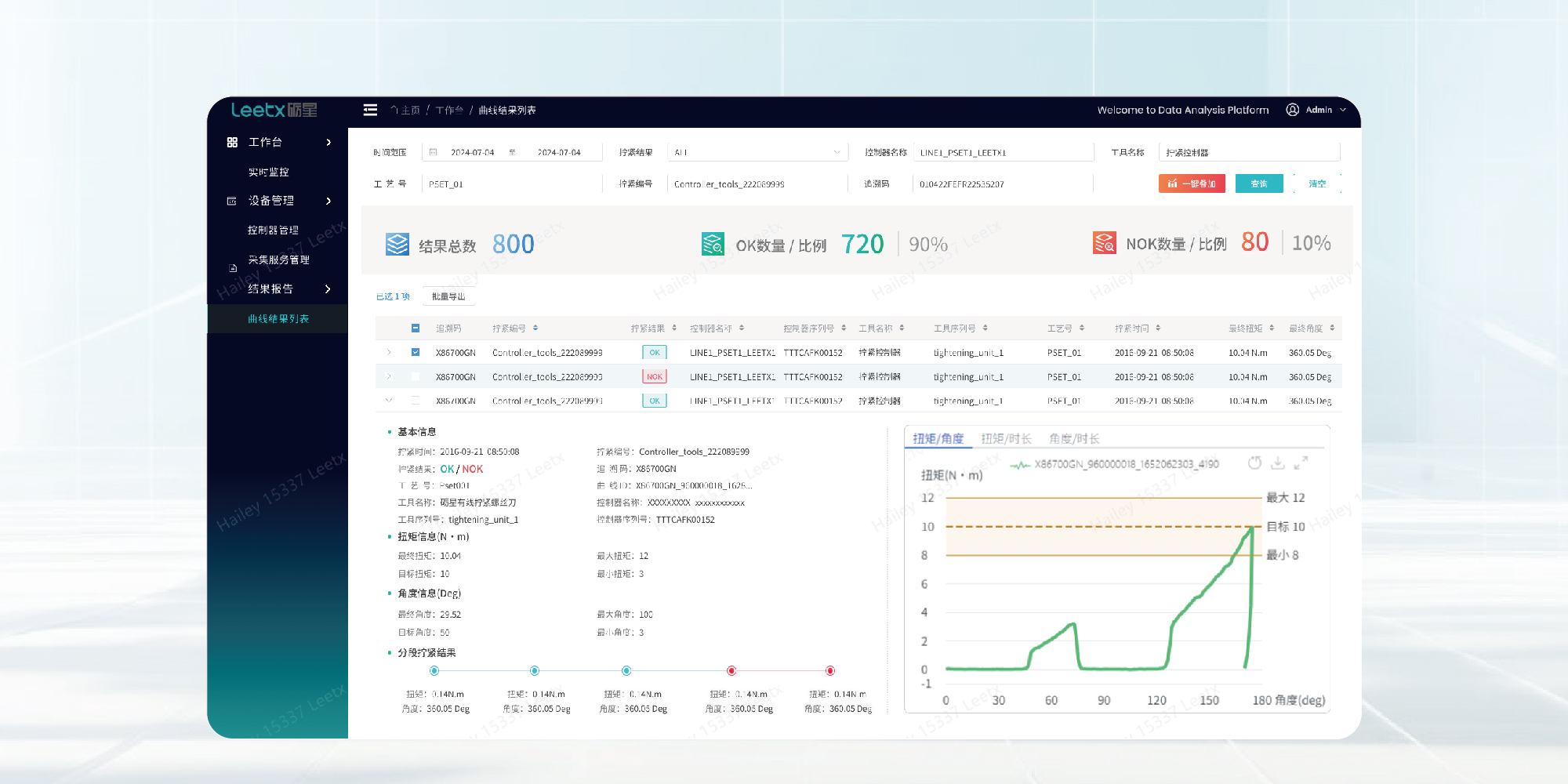
A pneumatic press leaves no record unless external sensors are added. A hydraulic press can be instrumented, but the instrumentation is an addition to the drive, not part of it. A servo press measures force and position as a condition of operating, so every cycle produces a force–displacement curve.
In the Leetx system the AEPS samples force at 10 kHz with 24-bit resolution and 1% system accuracy, and the evaluation system records curves, applies evaluation windows and trigger zones across the stroke, and stores results for traceability. The curve is the inspection record; the drive type decides whether it exists at all.
Comparison Summary
When a Servo Press Is Not Required
The comparison does not make servo the answer to every press. A pneumatic press remains the right choice for low-force, low-precision operations with no monitoring requirement, where its simplicity and cost are decisive. A hydraulic press remains the right choice where force requirements exceed what a servo press offers, or where a simple high-force operation needs no record.
A servo press is the right choice when the process needs a controlled approach, a force profile rather than a force value, a defined completion condition, or a curve per part. Those are the requirements of precision press-fit, which is why the drive type matters there more than elsewhere.
Reading the AEPS Force Control Figures
For buyers comparing servo presses on force control, the AEPS figures are read as follows:
- Force range 2–500 kN, specified per application. The force sensor is sized to the working force, so the stated accuracy applies where the process operates.
- 1% system accuracy, 24-bit resolution, 10 kHz sampling. Accuracy describes how close the measured force is to the applied force; resolution is the smallest increment; sampling rate is how often it is read. The three are different properties, and accuracy is the one to confirm against the working load.
- 0.01 mm positioning repeatability for the press itself. Requirements tighter than 0.01 mm call for an external displacement sensor, rather than an optional precision setting on the press. System performance must be verified in the actual application, taking tooling rigidity, part location and the measurement setup into account.
- Overshoot within 1%. A property of the evaluation system's adaptive deceleration, confirmed on the actual part during trials.
Leetx sizes the AEPS and configures the evaluation system from part drawings, fit tolerances, process force and stroke, and validates the force profile on the customer's parts before the station is fixed. To compare drive options for a specific press-fit, share those inputs with Leetx.
FAQ About Servo, Hydraulic and Pneumatic Presses
Q1: Is a Servo Press Always More Accurate Than a Hydraulic Press?
In force and position control, yes, because force is a controlled variable with continuous feedback rather than a consequence of pressure. The accuracy that reaches the part still depends on fixture rigidity and part location, which apply to all three drive types.
Q2: Can a Hydraulic or Pneumatic Press Record Force–Displacement Curves?
Only with added sensors and a separate monitoring system. A servo press measures force and position as a condition of operating, so the curve is produced for every cycle without additional instrumentation.
Q3: What Force Range Does the Leetx AEPS Servo Press Cover?
A standard range of 2–500 kN, with force and stroke specified per application and customization for non-standard requirements. The appropriate size is chosen against the process working force.