
















Blow-Feed Screwdriving: Which Screws Can Be Blow-Fed, and Where Feed Tubes Fail
Key takeaway: A screw can be blow-fed when it keeps one orientation inside the feed tube and arrives at the working head in a state the head can hold. Leetx checks this in two steps: the ratio of screw length to maximum head or washer diameter, and, where the ratio is marginal, the angle at which the screw can turn inside the tube. Screws that fail both checks go to pick-and-place feeding instead.
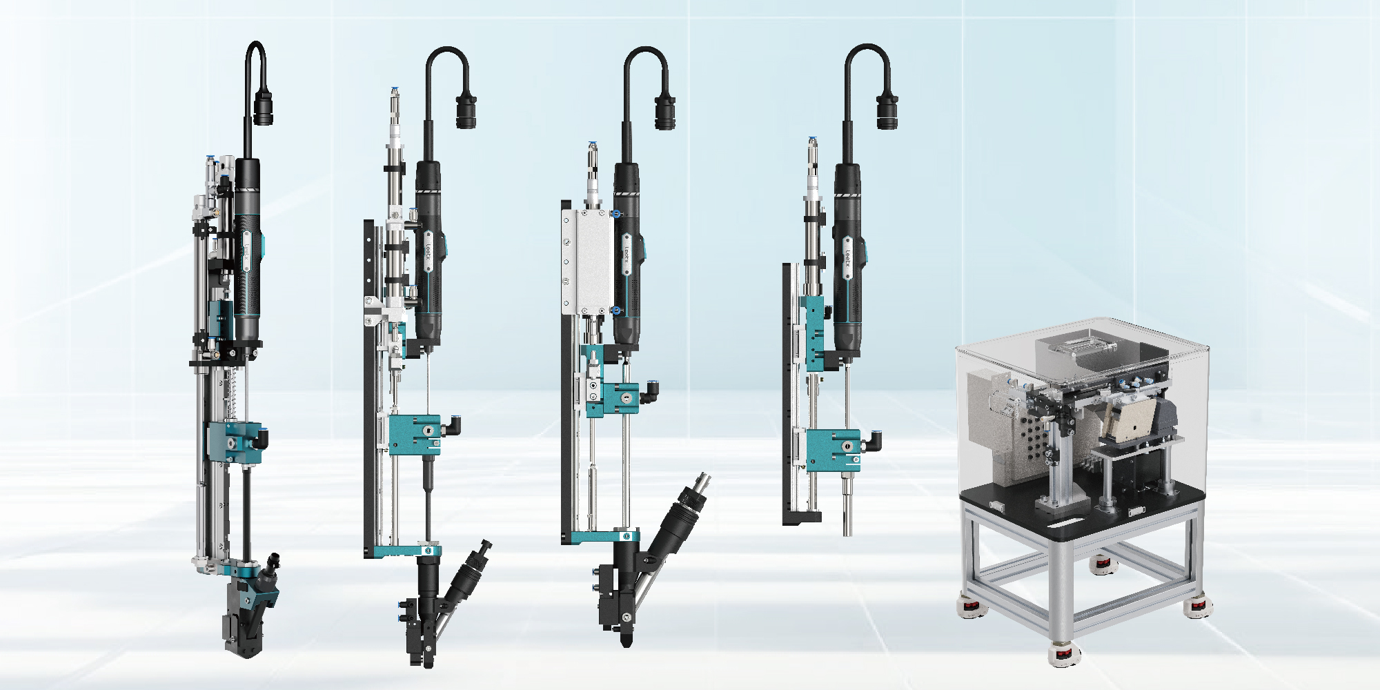
Most blow-feed problems in production are not caused by the screw. They come from tube routing that changed after installation, from a head that does not match the joint access, or from a feeding sequence that does not confirm arrival before the next request. Leetx's Automatic Screw Feeding System covers the chain from hopper to joint with the ASG standard blow-feed module, the AIV-AT and AOV vacuum modules for obstructed joints, step and bowl feeders, tube accessories and the FSC-2000 feeding controller, rated at 1.5 s per screw, a jamming rate below 0.01% and a feed tube life of over 1 million cycles.
Which Screws Can Be Blow-Fed
Blow feeding pushes a single screw through a flexible tube with compressed air. Whether the screw arrives correctly depends on four properties of the fastener:
Two details decide most cases. First, the ratio is calculated against the head, not the thread: an M3 pan-head screw 4 mm long has a ratio of 1.33 on thread diameter but about 0.7 on its 5.6 mm head, and will tumble. Second, for a combination screw the washer sets the diameter, because the washer is the widest part that has to pass every bend and the receiving jaw.
Leetx feedability analysis: ratio first, passing angle second
Where the ratio falls below the screen, Leetx does not reject the screw outright. The second check is the passing angle: the angle to which the screw can tilt inside the feed tube, calculated from the screw dimensions and the tube's inner diameter. A screw that cannot tilt far enough to turn over will still feed reliably even at a low ratio. Where both checks are marginal, Leetx engineers assess the fastener on the actual tube and module before the station design is fixed.
This two-step analysis is the reason tube inner diameter is matched to the screw rather than specified as a universal clearance. The tube is part of the feedability calculation, not an accessory chosen afterwards. Screws that fail both checks, including very short screws, wide truss heads and nuts, are handled by pick-and-place feeding.
What a Blow-Feed Screwdriving System Consists Of
From hopper to joint, a Leetx blow-feed system has five parts, each with a defined handover to the next:
The ASG is the default module where the jaw can approach the joint. Its stroke assembly includes fall prevention, the bit is integrated, and the swing-arm head is released quickly for jam clearance. It is sized by the screw's maximum head or washer diameter, and Leetx's selection combines the screw description (type, drive, size) with the module size to form the order code.
How the modules fit inside the complete screwdriving station is covered in automatic screwdriving system components; how screws are evaluated for feeding in general is covered in evaluating automatic screw feeding systems.

Where Feed Tubes Fail After Installation
A short, straight test route does not represent a production machine. Installed tubing passes around frames, guarding and moving equipment, and its shape changes with tool position. The interruptions that appear in production usually trace back to one of five places:
Three routing rules prevent most of the first two rows:
- Avoid tight bends. A screw turns over where the tube bends sharply; route with generous radii and never strap the tube hard against a robot wrist.
- Keep the tube off vibrating structures. A tube that shakes with the machine loses the screw's alignment mid-flight.
- Use dry, oil-free air. Oil mist inside the tube collects dust and metal fines and causes chronic mid-tube jams.
Check access for inspection and replacement as well as the initial route: a tube that is hard to reach turns an occasional interruption into a long recovery. Between batches, the cleaner clears residual screws from a shared path.

Tightening Interference: Matching the Head to the Joint
Delivery to the head and access to the joint are two different questions. Leetx's feedability analysis ranks joints by interference: an interference-free surface, interference on one side, interference on several sides, and counterbore interference, in increasing order of feeding complexity.
- Interference-free surface. The ASG jaw approaches directly; the jaws need clearance around the screw to open and eject it during tightening.
- Interference on one side. An extended jaw design or an approach at a specific angle clears the obstruction with the ASG.
- Interference on several sides, or a counterbore. The jaw cannot approach. The AIV-AT receives the blow-fed screw and holds it by vacuum in a tube that can match the screw-head diameter, with suction detection before the drive starts, adjustable downward force and screw drop prevention, for heads up to 14 mm. The AOV does the same for external-drive screws with a floating socket that aligns to the head before torque is applied.
Where interference is unavoidable, the product can still be designed for feeding: locate the tightening position in a clear area where possible, change the assembly sequence, or change the attitude of the workpiece. These are design decisions made before the module is selected.

Feed Rate and Station Cycle Time
Faster delivery reduces cycle time only when delivery is the limiting step. Tool travel, clamping and tightening often occupy more time, and preparation can overlap with them where the machine design allows.
If screw preparation takes 0.8 s and an independent operation takes 1.2 s, full overlap occupies 1.2 s and serial execution 2.0 s. The gain comes from the sequence, not from a faster feeder. Measure request-to-ready time alongside total station cycle time, and include delays and recovery rather than only the fastest successful transfer. Where the feeder is remote, a buffer at the module is usually the cheaper fix than a faster feeder.
What a Blow-Feed Acceptance Trial Includes
Use the intended screw from a production lot, representative tube routing and the receiving module. Run the relevant tool positions, including the most distant one, and include replenishment, routine access and restart conditions. The trial establishes:
- Arrival. The screw reaches the head in the intended orientation at every tool position tested.
- Retention. The head holds the screw through approach and engagement; on vacuum modules, suction detection confirms it.
- Surface condition. Coated or appearance-sensitive screws show no contact marks after feeding.
- Timing. Request-to-ready time is measured against the station sequence, including the slowest position.
- Recovery. After a deliberate stop, the sequence establishes whether a screw is in transit or at the receiver before the next request.
Leetx runs this trial with the customer's screws, workpiece geometry and intended tool motion, and proposes the feeder, module and tube layout together. To assess a blow-feed application, share screw samples or drawings, the space around the joints and the machine layout with Leetx.
FAQ About Blow-Feed Screwdriving
Q1: What Is the Largest Screw a Blow Feeder Can Handle?
It depends on the module and feeder, not on thread size alone. The receiving head is sized by the screw's maximum head or washer diameter; the Leetx ASG and AIV-AT product pages state heads up to 14 mm. Larger fasteners are assessed per application.
Q2: Can a Blow-Feed System Handle Screws With Captive Washers?
Yes, within the module's diameter range. The washer sets the diameter used in the feedability analysis, and it must sit flat against the head before separation. Leetx rates jamming below 0.05% for screws with pre-assembled washers against 0.01% for plain screws.
Q3: Can One Blow-Feed Line Supply Different Screw Types?
Each screw must suit the delivery and receiving components, and the process needs a defined way to clear the path and select the correct program. Mixed production and batch changeover are different requirements; the options are covered in quick-change screw feeding.
Q4: Which Leetx Module Is the Standard Blow-Feed Module?
The ASG, which receives the blow-fed screw in a sprung jaw for accessible joints, with a head that rotates 200° and jaws that rotate 360° to clear interference. Where the joint is recessed or obstructed on several sides, the AIV-AT or AOV vacuum modules take over the holding function.