
















Torque Control or Angle Control for Industrial Tightening?
In brief: Use torque control with angle monitoring on hard joints with consistent friction and a torque specification. Use angle control with torque monitoring, counted from the seating point, on soft joints, long bolts and joints specified by clamp load. Use slope control on fasteners specified to yield. The choice depends on joint stiffness, friction scatter and how the specification is written.
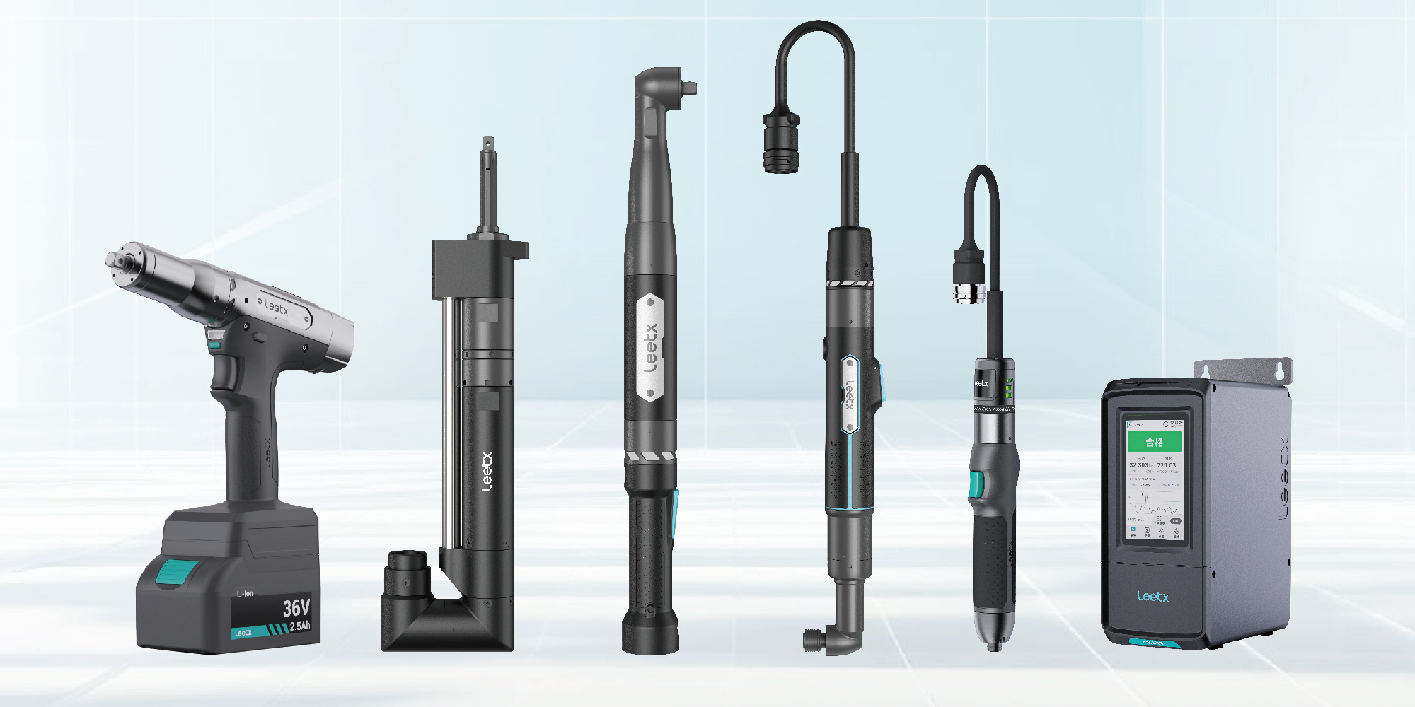
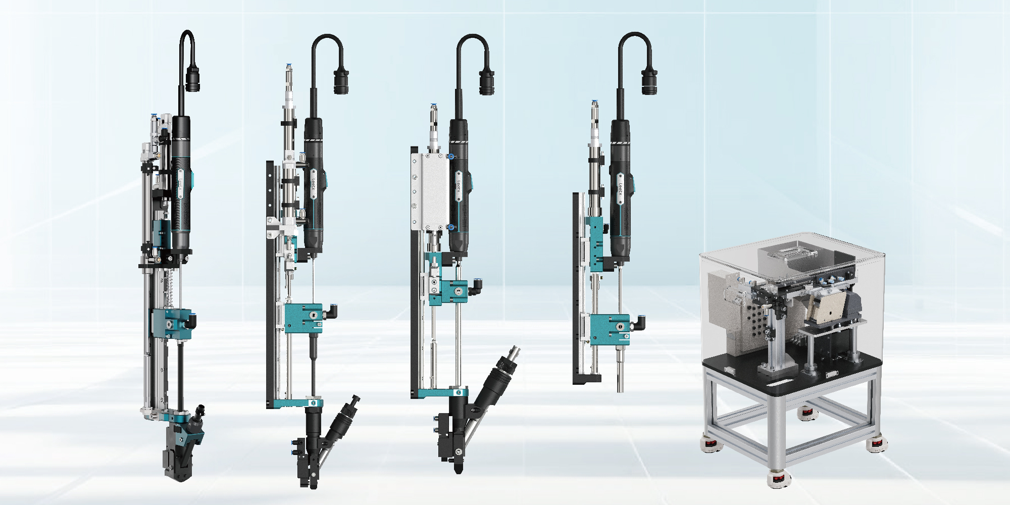
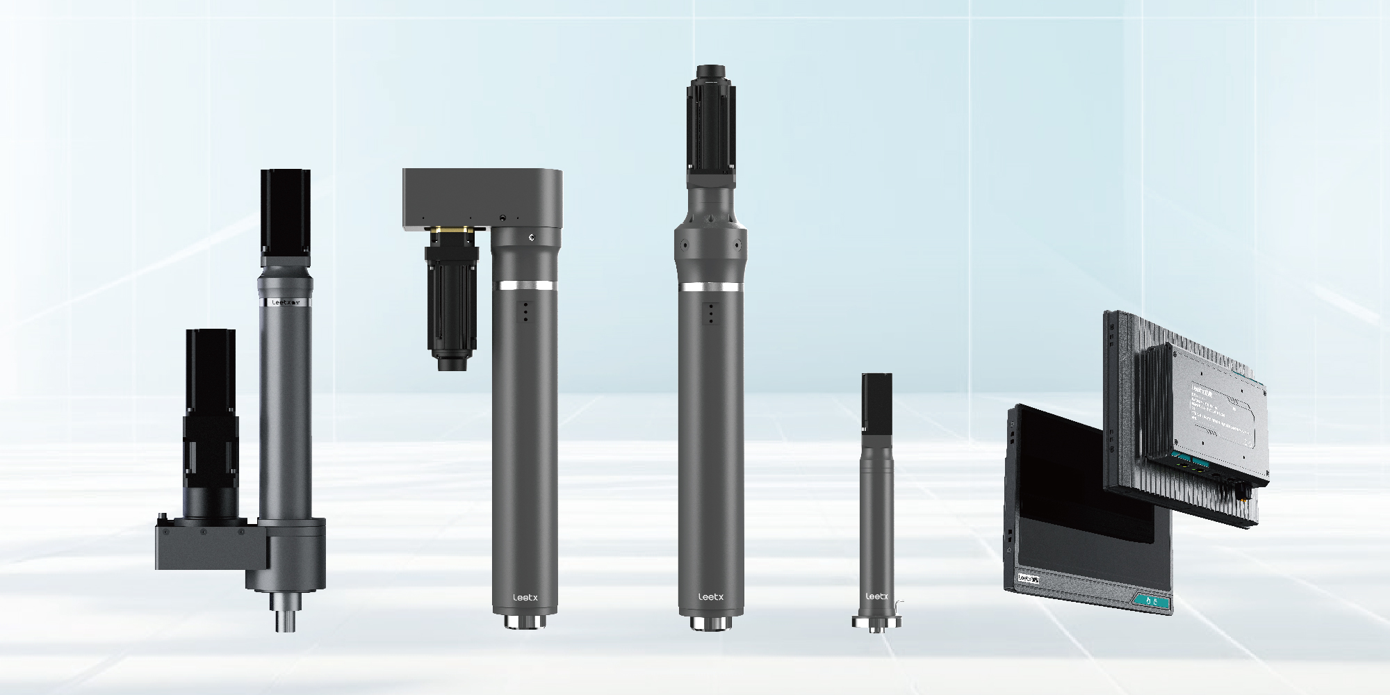
The two strategies differ in what ends the tightening and what the second measurement is used for, and the second measurement is only meaningful when its reference is defined. Leetx transducerized tools support torque, angle, seating-point and torque-slope control through the TCS.2000 controller for corded tools and the WCS.2000 for cordless tools, with 200 programs of 25 steps, 99 JOBs and curve sampling at 1000 Hz. Which strategy suits which joint type is introduced in selecting an industrial tightening system; this article covers the choice in detail.
Which Joint Needs Torque Control, and Which Needs Angle Control
Hard joint, consistent friction, torque specification → torque control with angle monitoring. Torque tracks clamp load closely on a metal-to-metal joint and the stop is sharp. The angle window adds the check that the torque alone cannot give: a missing washer, a cross-thread or a damaged thread changes the angle to seating while torque still reaches target. This is the default on most assembly lines.
Soft or long joint, or clamp-load specification → angle control from the seating point. Where the joint compresses, where the bolt is long, or where friction scatters, the same torque corresponds to a wide range of clamp load. Rotation after seating stretches the bolt by a geometric amount regardless of thread friction, so angle gives the more consistent clamp load. Its weakness is the reference: if seating is reached inconsistently, the scatter is in the measurement, not the joint.
Fastener specified to yield → slope control. The controller detects the change in the torque–angle gradient as the fastener yields and stops there. It gives the highest preload the fastener can carry with the smallest scatter, at the cost of a fastener that is not reused and a program validated for that fastener and lubrication.
The joint table from the application review decides, not the catalogue. Two joints with the same torque target can need different strategies.
Torque Control vs. Angle Control: Strategy Comparison
Angle monitoring does not control the stopping point. In a torque-controlled cycle the tool stops at torque; an acceptable torque with an unusual angle flags the cycle for investigation. In an angle-controlled cycle the roles reverse.
Advanced Strategies on the TCS.2000 and Where They Apply
Beyond the controlling strategy, four advanced functions each solve a specific production problem:
Steps available within a program include socket recognition, fast rundown, sync, wait, socket release and seating-torque monitoring. Sync and wait let up to 20 EFS spindles reach each stage together before the next, which matters on sealed covers and flanges.
Angle Reference: Where Torque-Angle Measurement Starts
The reference is part of the measurement definition. The same tightening reports a different angle depending on where counting begins:
An angle without its reference cannot be compared with anything. A threshold torque has to be selected and validated for the joint; if it is reached inconsistently before stable seating, part of the apparent angle variation comes from the definition itself.
Leetx controllers can use the detected seating point as the reference. Seating-torque detection identifies where resistance rises sharply as the parts come together, and the final-stage angle counts from there, which removes the dependence on a fixed threshold where the joint seats consistently. The reference is documented with the limits; when a program is transferred, the destination has to use the same definition, not the same number.

Reading the Torque-Angle Curve
The curve shows what a final torque value conceals. Three features point in known directions:
- Earlier torque rise: engagement or seating; a foreign object under the head, a cross-thread, a damaged thread.
- Additional rotation: component compression, stack-up, a missing washer, or a changed reference.
- Changed slope: a different lubricant, a different material, a yielding fastener.
These are investigation directions, not diagnoses. Compare the region with physically accepted assemblies and inspect the components before changing settings.
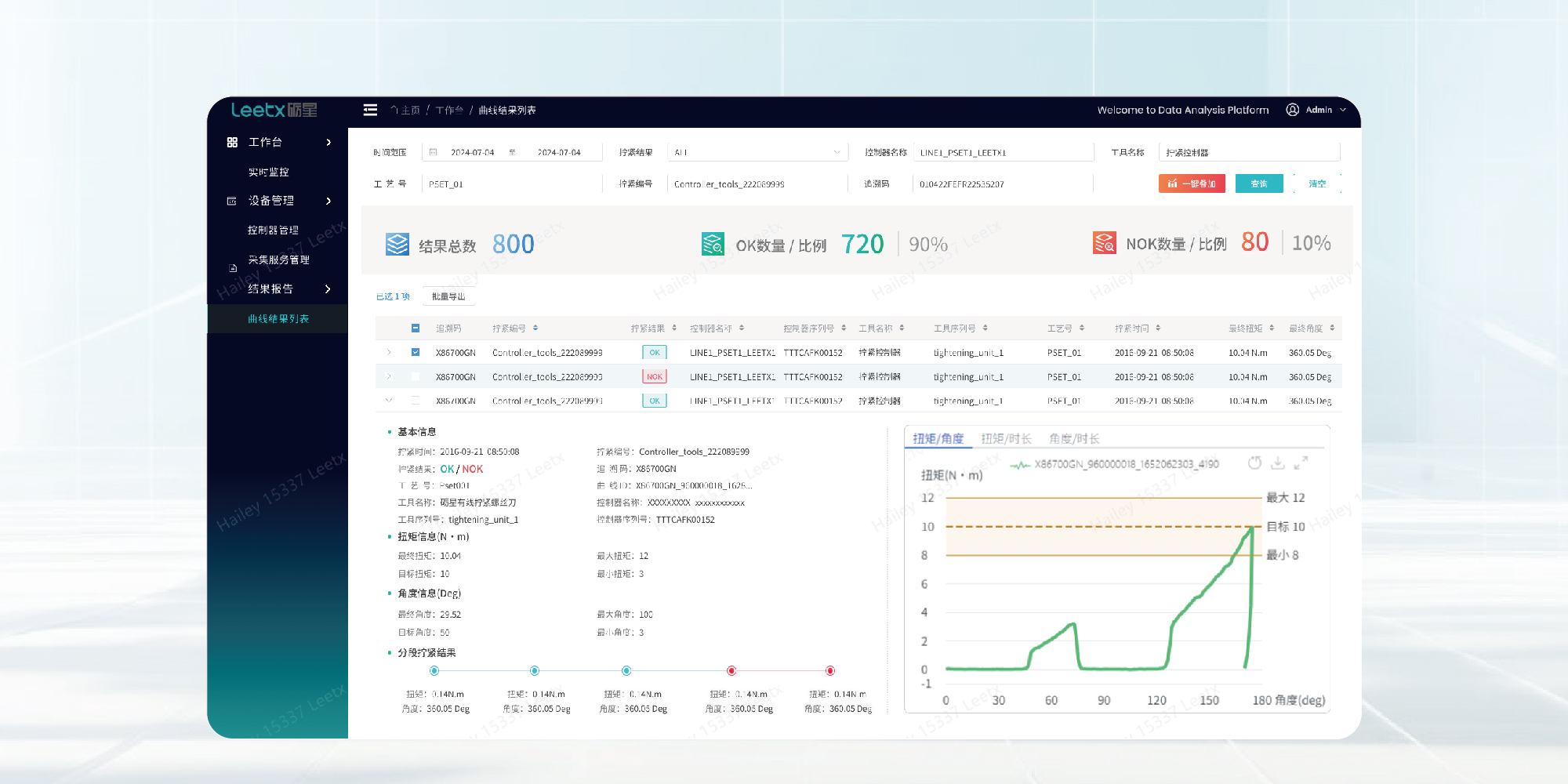
The TCS.2000 generates the curve step by step at 1000 Hz, so each stage is judged on its own segment, and displays the termination reason: target reached, angle limit exceeded, torque limit exceeded, operator release, tool fault. Four curve types are available: torque–angle, torque–angle–time, speed, and process-chain monitoring that identifies which step failed. The sampling rate is what makes slope control and overshoot adaptation possible; a hard joint develops torque in tens of milliseconds, and a slower sample rate misses the gradient.
Setting Torque and Angle Limits From Joint Data
Limits belong to the population of accepted joints, with the defects the station must catch placed outside them.
- Collect accepted data. Tighten parts accepted by the product's own verification method, across the relevant component and operating variation, including tolerance extremes.
- Set the window around the population. Not around one good result plus a convenient percentage. A narrow window is not a more capable process; it may only reject normal variation.
- Test the window on defects. Each defect in the test plan has to fall outside the window or trigger a separate detection.
- Write the specification. Controlling strategy, angle reference, speed stages and their triggers, evaluation interval and limits with the data behind them, calibration coefficients, component and fastener versions, lubrication, socket or bit, extension, and the NOK recovery procedure.
A capability assessment supports step 2 where its assumptions hold. NIST's process capability guidance separates spread from centring: Cp compares specification width with six standard deviations, Cpk also accounts for the mean's distance to either limit. A capability figure for final torque is not one for the finished joint, and no index validates a wrongly chosen angle reference.
Calibration keeps the limits meaningful. The TCS.2000 holds ten calibration coefficients for different target torques on one tool, which matters on wide-range tools such as the NRA.450 (90–450 N·m), and derives a new coefficient from five reference values, so periodic recalibration is routine work.
Speed Stages in Torque-Angle Tightening
A program uses different settings for rundown and final tightening. Fast rundown shortens the cycle; a slow final stage lets the controller stop accurately on a hard joint and lets the angle count cleanly on a soft one. The transition decides how the tool arrives at the part of the cycle where control matters.
Assess speed changes on the actual assembly: a faster rundown that changes seating behaviour needs more than a cycle-time comparison. Where the program switches control conditions, establish what triggers the next stage and which limits apply there. With 200 programs of 25 steps, the transition is defined per joint rather than compromised across joints.

Three Mistakes That Produce False NOKs
The angle reference is not recorded. A window set from a seating-point reference is applied on a station counting from a threshold torque. The numbers match; the measurement does not. Record the reference with every limit.
Limits are copied between stations. A program validated with one socket, extension and speed profile is loaded on a station with a different one. Bit torsion, reaction and rundown behaviour change the angle. Re-validate on the destination, or use angle compensation where the difference is a long bit.
Speed is changed without re-validation. A faster rundown moves the seating point on a soft joint and the window no longer fits. Treat a speed change as a program change.
Leetx configures the strategy, reference and limits with the customer's joints during application review and keeps the trial curves so that windows are set against real variation. Release and NOK handling on critical joints are covered in transducerized tightening tools for safety-critical joints; record organisation across program revisions in tightening data collection and traceability. To discuss a joint where the strategy is not yet settled, share the joint drawing, tightening specification and any existing curves with Leetx.
FAQ About Torque and Angle Control
Q1: Is Angle Control More Accurate Than Torque Control?
Neither is more accurate in general. Angle control reduces the influence of friction on clamp load once the reference is reliable; torque control is simpler to specify and verify. The joint's behaviour decides which gives the more consistent result.
Q2: When Should I Use Torque Plus Angle Tightening?
On any joint where the final torque alone cannot distinguish a good joint from a defective one. Missing washers, cross-threads and damaged threads all change the angle to seating while still reaching torque, which is why torque control with angle monitoring is the default on most assembly lines.
Q3: Can Angle Limits Be Copied Between Stations?
Only if the destination uses the same angle reference, speed stages and tool configuration. The numerical limits mean nothing without the definition behind them.
Q4: Which Tightening Strategies Does the Leetx TCS.2000 Support?
Torque control, torque control with angle monitoring, angle control with torque monitoring, slope control and angle compensation, with fast rundown, overshoot adaptation and seating-torque control as advanced functions, in programs of up to 25 steps.