
















Transducerized Tightening Tools for Safety-Critical Joints: A Specification Guide
Short answer: Choose a transducerized tightening tool when the joint is safety-relevant, when torque and angle both have to be verified, and when every tightening must be traceable. A current-controlled or clutch tool is sufficient where the joint is stable, the risk is limited and torque control alone is required. The choice depends on how critical the joint is, which defects have to be detected, what data is required, and the consequence of one wrong tightening leaving the line.
The fundamental difference between the two tool types is where the torque information comes from. A transducerized tool measures torque and angle with an integrated sensor; current-controlled and clutch tools derive torque from motor current or limit it mechanically. That difference decides whether the tool can detect faults such as cross-threading and missing washers, whether it generates a complete tightening curve, and whether it keeps a record for every bolt.
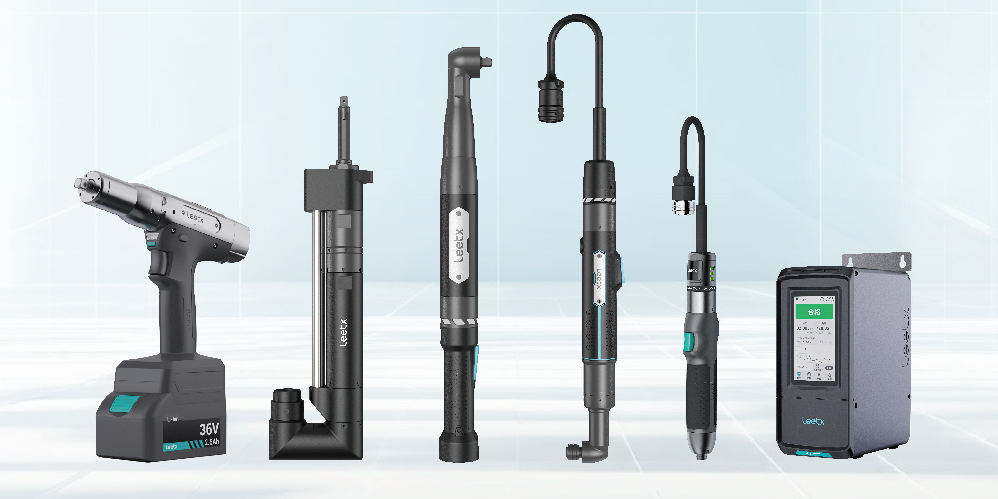
Leetx's Transducerized Tightening System covers EHS/EHA screwdrivers, NRS/NRA nutrunners and EFS spindles on the TCS.2000 controller, EWP/EWA cordless tools on the WCS.2000, and the Datainsight data traceability system. Tools, controllers and software are developed in-house.
Transducerized vs. Current-Controlled and Clutch Tools
A clutch tool is adequate where the joint never changes and a periodic check is enough. A current-controlled tool adds programmable stages and an OK/NOK judgement, but its torque reading drifts with friction, bit wear and temperature because it is an estimate. A transducerized tool is chosen when the reading has to reflect the joint rather than the motor.
Leetx rates its transducerized tools at 6σ ±5% and its EFS fixtured spindles at ±3% under ISO 5393 laboratory conditions. Each tool pairs the torque transducer with current protection as a second monitoring channel, so a sensor fault is detected rather than passed through, and long-term torque consistency is verified in Leetx's own laboratory testing.
What a Torque Transducer Measures in a Safety-Critical Joint
The transducer measures torque at its position in the drivetrain and feeds it back in real time; the encoder adds rotation. Together they show how much torque built over how much rotation, and where the parts seated.
The transducer does not measure clamp load. Friction at the threads and under the head decides how much torque becomes clamp force, and friction changes with coating, lubrication and part condition. NASA-STD-5020A cites historic preload uncertainty of ±25% for lubricated and ±35% for non-lubricated bolts under torque control. The figures are from aerospace; the conclusion applies to any line: torque alone does not prove the joint is clamped.
Angle from the seating point closes that gap:
- A missing washer shortens the angle to seating.
- A cross-thread lengthens it and raises torque early.
- A damaged thread changes the slope.
Torque alone shows that the target was reached. Torque plus angle shows whether it was reached in the expected way.
Leetx Tools for Safety-Critical Joints
The tool for a joint follows torque, access and who positions it. The Leetx corded range on the TCS.2000 covers the three cases; the cordless range on the WCS.2000 covers work away from a fixed station.
EHS and EHA screwdrivers, 0.3–22 N·m
For electronics, battery module covers, brackets and trim. The EHS is straight; the EHA is angled for restricted access. Both carry a high-precision torque transducer, a three-colour LED ring that shows OK/NOK at the tool, an LED headlight, push-to-start and a reverse button. An ESD version is available for 3C electronics and EV battery, drive and control assembly.
NRS and NRA nutrunners, 5–450 N·m
For seat mounts, battery pack covers, subframes, suspension and chassis joints. The NRS is straight for open, axial joints to 65 N·m; the NRA is angled for restricted and side access to 450 N·m, with a bevel-gear head and planetary reduction. From the NRA.280 upwards, a reaction arm and balancer are part of the station.
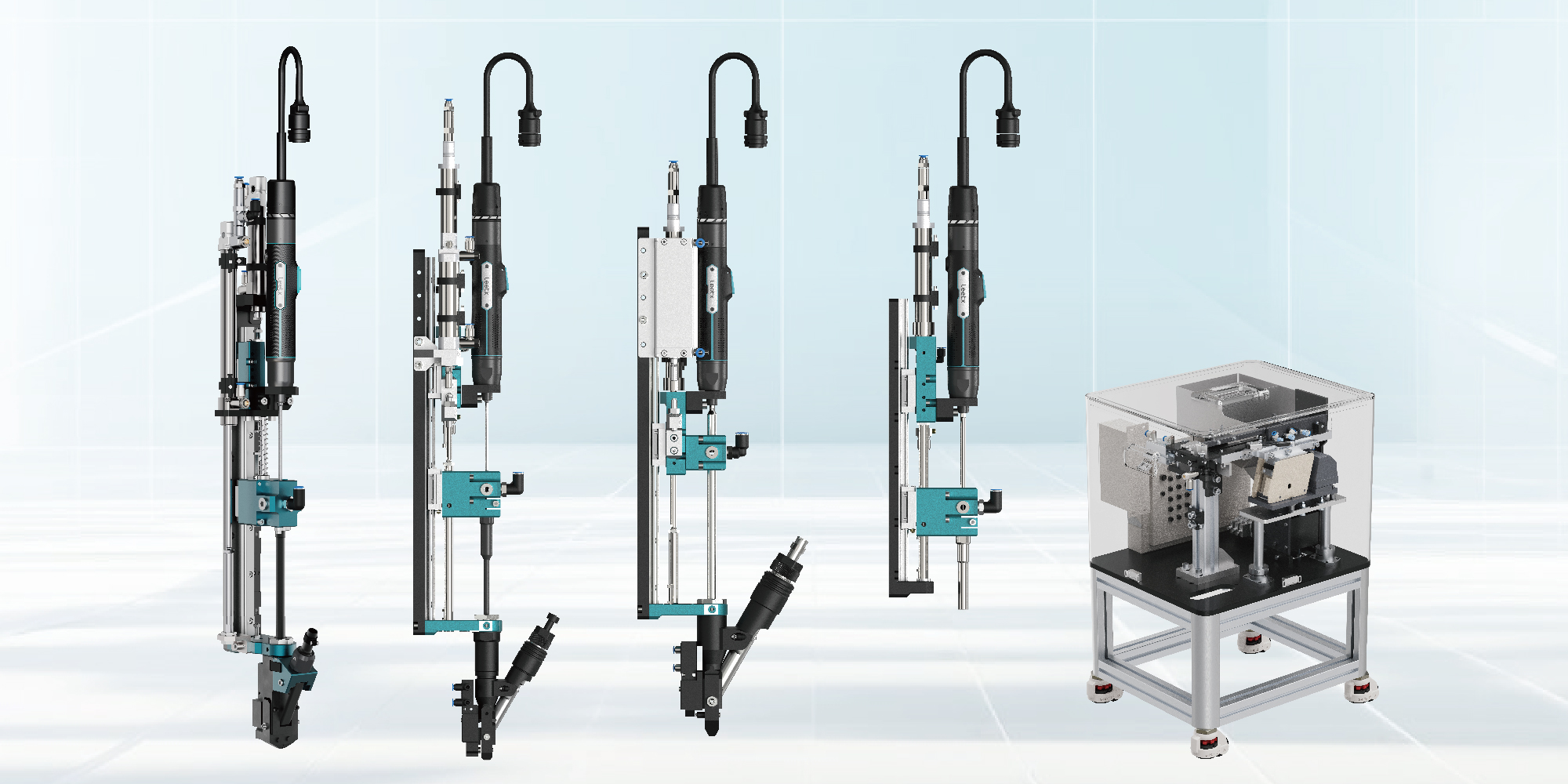
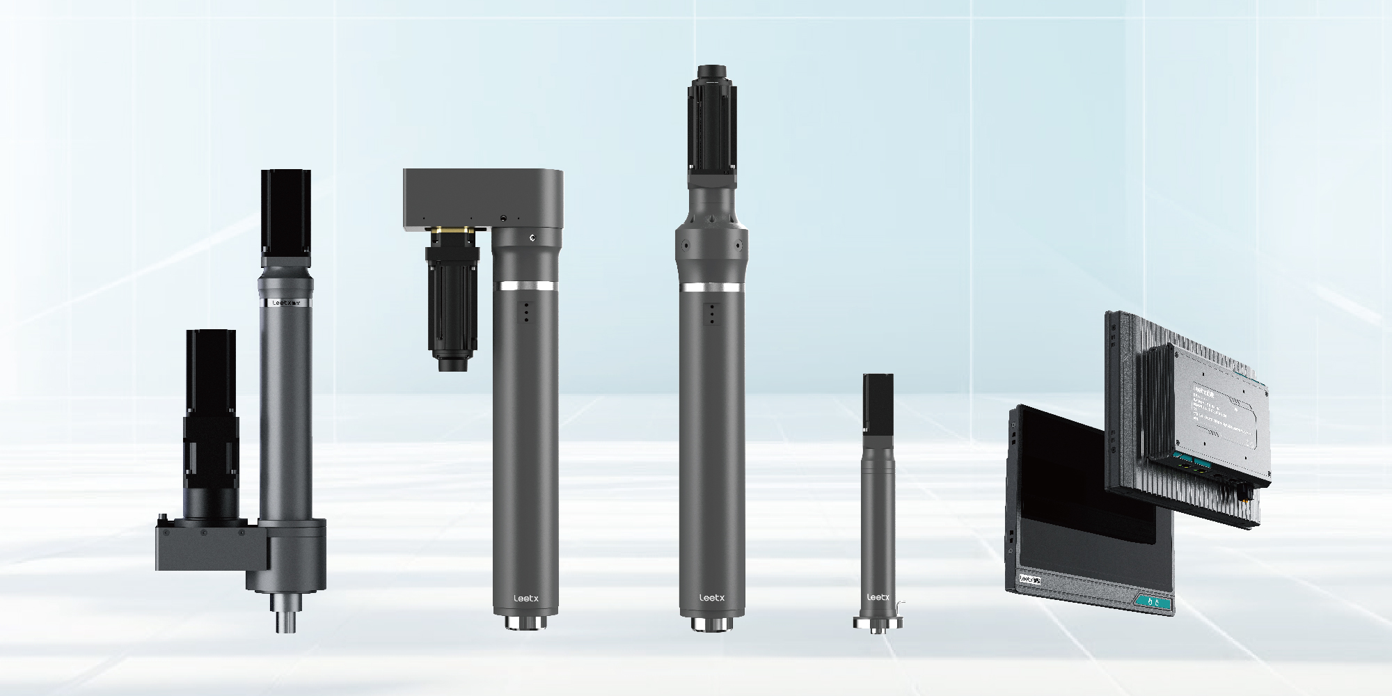
EFS fixtured spindles, 4–500 N·m
For automated stations: battery pack lids, cylinder heads, hubs and flanges with several bolts tightened together. The spindle carries the transducer, a telescopic output head as standard to absorb bolt sink and part tolerance, and standard or customised output heads. Up to 20 spindles synchronise in a master–slave group; any controller is set as master in software, with no separate master unit. Models run from EFS.020 (4–20 N·m) through EFS.050, EFS.090, EFS.150, EFS.280 and EFS.360 to EFS.500 (100–500 N·m).
EWP and EWA cordless tools, 0.5–105 N·m
For work around a large assembly where a cable is impractical. The EWP pistol series (EWP.003, .008, .015) covers 0.5–15 N·m; the EWA angle series (EWA.032, .050, .070, .105) covers 6–105 N·m. Tools store results on board and re-send data recorded during a disconnection; one WCS.2000 manages up to 10 tools.
Corded tools use high-flex drag-chain cable rated for more than 10 million bend cycles, shielded to protect the millivolt transducer signal from drive and welding interference, with aviation-grade connectors on nutrunners and spindles.
Four Requirements for Tightening a Safety-Critical Joint
The transducer handles measurement. It does not know which workpiece is under the tool, and a controller can judge a cycle without the line acting on it. Keeping the four requirements separate shows the integration work before commissioning and makes supplier discussions concrete: who implements each function, and who verifies it.
Identifying the operation
A joint on a mixed-model line gets the wrong program in two ways: the wrong variant is selected, or the right program runs on the wrong fastener.
- Variant: select the program from a scanned barcode or a PLC signal, not an operator menu. The TCS.2000 binds a 128-byte barcode to the result for program selection and traceability.
- Position: a torque arm with position sensing tells the controller which hole the tool is over, so a joint is neither skipped nor tightened twice.
- Sequence: put the required order into a JOB. Where several spindles must reach each stage together, as on a sealed cover, use the sync and wait steps.
Matching the strategy to the joint
The TCS.2000's advanced strategies address the defects that matter most on critical joints:
- Seating-torque control for self-tapping screws and self-locking nuts. Rundown resistance has nothing to do with clamp load; the controller identifies the seating point and controls the increment after it.
- Slope control uses the torque–angle gradient. Stripped threads, cross-threading, missing washers and foreign objects can pass a final torque and angle check; the slope shows them.
- Angle compensation for long bits on automatic feeding stations, where bit torsion would otherwise be read as joint rotation and cause false NOKs.
- Overshoot adaptation for high-speed applications, so the stop lands on target.
- Fast rundown for long bolts, followed by a controlled final stage.
Which of torque and angle should be the controlling variable is covered in torque control or angle control.
Deciding which defects must be detected
Start from the risk assessment: list the defects the station has to catch and assign a measurement to each.
Add the checks the risk list requires, not the maximum the software allows. Every window has to be validated and maintained.

How to Validate a Safety-Critical Tightening Process
Validation has two halves: prove that accepted parts behave consistently, then prove that the defects on the risk list are caught.
Step 1 – Establish the accepted process
- Run the intended program on representative parts, including parts from the tolerance extremes.
- Confirm the physical result with the product's own acceptance method, not with the tool's OK.
- Record the full curve for every part.
Step 2 – Challenge the limits
- Test each defect on the risk list through an approved plan.
- Do not assume every bad joint produces an obvious curve; a defect that passes needs a second check.
Worked example: M8 bracket bolt, 25 N·m, hard joint
Step 3 – Keep one validation record
- Component and fastener versions, surface preparation, lubrication
- Tool, controller, socket or bit, extension, fixture
- Program revision, speed stages, angle reference, calibration coefficients
- Acceptance method and measured results
- Conditions tested and open questions
The TCS.2000 holds ten calibration coefficients for different target torques on one tool and derives a new coefficient from five reference values, so recalibration after a tool check is routine work.
One convenient batch proves feasibility, not production variation; state which it was. The general trial method for a tightening configuration is covered in selecting an industrial tightening system.

NOK Handling for Safety-Critical Tightening
A NOK result needs a defined next step: hold for review, send to rework, or run an authorised recovery procedure. Tightening again until the result reads OK is not a procedure; the second attempt changes the joint, and its reading does not explain the first.
- Decide whether the fastener may be reused, which components are replaced, and who authorises the next operation.
- Keep the first attempt and the rework distinguishable; the tightening ID and batch number on each result make that possible.
- On cordless stations, NG lock on the WCS.2000 holds the tool after a failed result until the cause is checked.
- On corded stations, the TCS.2000 passes OK/NOK to line control and the station program decides whether the part moves.
Missing data is its own state. A communication drop, an incomplete cycle and a completed NOK are different events, and recovery has to establish what happened to the joint as well as what the controller recorded. WCS.2000 tools re-send results recorded during a disconnection, so a dropped link does not become a missing record.
Tightening Records and Traceability Data
Every cycle on a Leetx controller records:
- Tool and controller status, tightening ID and batch
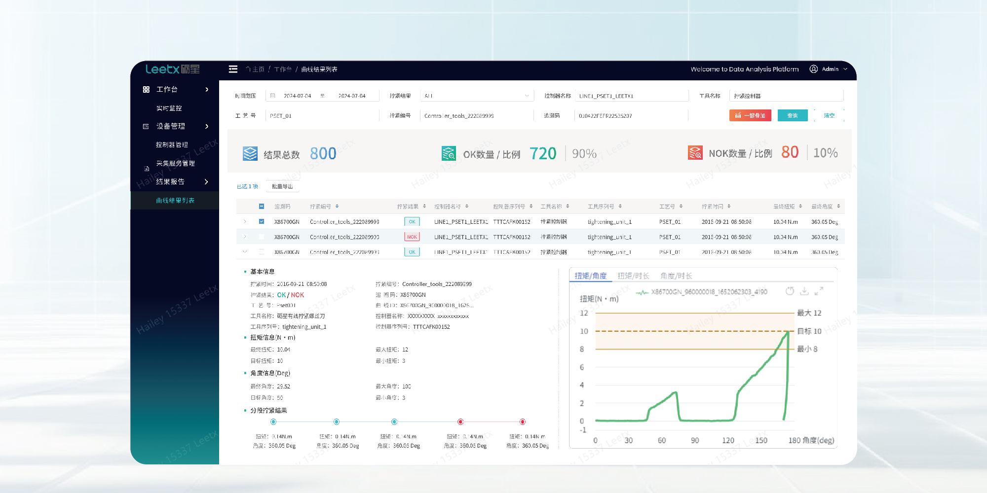
- Result, global angle, final angle, final torque, termination reason
- The curve in four forms: torque–angle, torque–angle–time, speed, and process-chain monitoring that locates which step failed
The TCS.2000 holds 100,000 results and 30,000 curves locally; the WCS.2000 holds 1,000,000 results and 100,000 curves.
Tightening results are uploaded in JSON format via HTTP to Leetx’s Datainsight data analysis software for statistical process control (SPC) analysis. Curves are transmitted at 1000 Hz, with segmented upload supported.
The TCS.2000 and WCS.2000 share one communication stack, so a plant running corded and cordless tools integrates one protocol into MES and trains engineers on one interface. Web-based programming reaches any controller by IP address, and permission control with a change log records who changed which program and when.
For retention beyond the controller, Datainsight archives results and curves on a server, runs SPC across stations and provides the station monitor. How results are bound to a workpiece and retrieved is covered in tightening data collection and traceability.

Tool Calibration and Process Change Control
Calibration covers the measurement system; process validation covers how the whole method performs on the joint. Neither replaces the other. Plan measurement checks, access permissions and program change control before production starts, and decide what happens when a tool check fails.
Re-validate when something changes the joint: a new coating, a new fastener supplier, a different material, a replacement extension, a modified speed. Any of these can move the seating point or the torque–angle relationship without touching the target torque. A program and its evidence travel together; the controller's backup and restore function keeps them together.
Specifying With Leetx
Send the joint drawing, fastening specification, expected variation, station layout and the result handling required. Leetx's proposal separates controller functions, optional equipment such as the fieldbus module, and integration work, and includes a trial on the customer's joints with the intended tool, socket and reaction arrangement. Trial curves are kept so that windows are set against real variation.
For automated stations, Leetx's tightening engineering team designs the station, torque-arm positioning or multi-spindle layout as a complete solution, with project management through commissioning, supported by Leetx's global service network. To start, contact Leetx.
FAQ About Transducerized Tightening Tools
Q1: Is a Transducerized Screwdriver More Accurate Than a Current-Controlled One?
It measures torque directly instead of estimating it from motor current, so the reading reflects the joint rather than the motor. Leetx transducerized tools are rated at 6σ ±5% under ISO 5393 laboratory conditions; confirm performance on your own joints with a capability study.
Q2: Can a Transducerized Tool Detect Cross-Threading or a Missing Washer?
Yes, through the angle to seating and the torque–angle curve, and most sensitively through slope control. The limits that catch them are set from accepted joints and tested on known defects.
Q3: Does a Transducerized Tool Certify the Finished Assembly?
No. A measured and accepted cycle is process evidence. Product compliance also depends on joint design, validation and production controls.
Q4: Which Tool Type Suits EV Battery or Automotive Safety Joints?
Leetx commonly uses EWP/EWA cordless tightening tools for battery pack cover fastening. Tool selection for battery modules and other automotive components depends on torque requirements, tool access and process validation.
Q5: What Happens to the Record if the Wireless Tool Loses Connection?
WCS.2000 tools store results on board and re-send data recorded during the outage once they reconnect. Whether the station keeps running during the outage is a station rule set in the specification.
Q6: Does Every Fastening Position Need Its Own Program?
Not always. Positions with the same validated requirement can share a PSET, and a JOB sequences PSETs across the assembly. Each position still needs its own identification so that completing one joint is not mistaken for completing another.